
Easy Does It
Engineered lifts and rigging gently handle specially made precast piping.

Dearborn Engineers & Constructors Inc. (Dearborn) recently teamed up with Ballard Marine Construction and Bay Crane Companies to plan the lifting and placement of special precast concrete pipe that will form the business end of a new freshwater intake for a city in metropolitan Chicago.
The precast-concrete intake pipe will reach about a mile out into Lake Michigan and lie on the lake bed about 50 feet below the water’s surface.
The outer end of the intake pipe will connect to three huge three-fingered intakes called tridents that will provide a total of nine water-intake openings.
This part of the project staged the tridents and their “Center Cross T” connecting section on a lakeside lot, then set all the pieces onto the barge that will float them to their installation site.
Ballard is the project’s prime contractor, Bay Crane Midwest is providing crane services, LGH is supplying rigging components and Dearborn companies provided ground analysis, engineered the rigging and collaborated with Ballard on lift planning. “It was a total team effort,” said Dearborn CEO Michael Walsh.
Special Pipe Needs Kid-Glove Treatment
Each trident consists of three pipes that connect to each other at one end and spread out like three up-curling fingers.
Each pipe, or finger, is about 5 feet in diameter, nearly 20 feet long and made of precast concrete.
Though this specialty precast concrete is strong, it can crack if over stressed.
The tridents’ sensitivity to stress, their unique shape and the one-year replacement time if one were damaged dictated that every aspect rigging, lifting and handling them had to be meticulously planned and carefully engineered.
“This job presented some really interesting challenges,” said Walsh. “The first was developing and engineering the load-handling concept and rigging to move asymmetrical, stress-sensitive, long-lead-time elements. The second was making sure the same rigging would work equally well both for the crane that would load the pieces from land onto the barge and for the barge-mounted crane that would later lower them to the lake bed for final assembly by divers. The third challenge was making sure that the land-based crane could work safely near the earth-and-sheet-pile dock.”
Firm Footing
One of Dearborn’s key jobs on this project was making sure the ground at the barge-loading site would support the 550-U.S.-ton capacity Liebherr LTM 1450-8.1 all-terrain crane that would be lifting the tridents and Cross T connector from land onto the barge.
To do that, Dearborn conducted a geophysical investigation and crane placement survey to locate and map any subsurface voids, underground utilities and structures such as seawall tiebacks and unconsolidated soils.
The survey also enabled Dearborn to assess whether the ground could support the crane reactions from lifting pieces that weighed more than 90,000 pounds with rigging.
Dearborn’s investigation used visual inspection, an aerial drone to inspect the seawall and a handheld radio detector and ground-penetrating microwave radar to check the ground to a depth of 12 feet.
The study revealed the locations of the buried tiebacks that support the sheet-pile seawall as well as underground utilities.
Avoiding all of those dictated in part where the crane could sit.
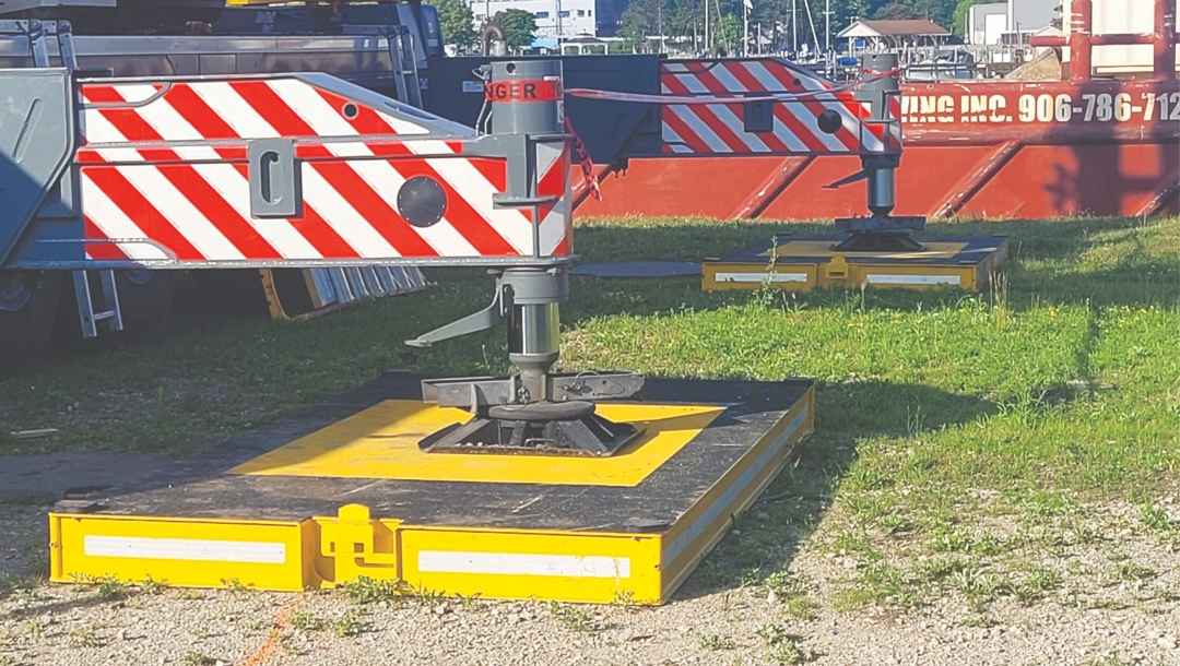
Dearborn’s analysis also recommended that the crane’s four outriggers be at least 20 feet from the seawall, and that each one be supported by a 6-foot-by-12-foot-by-8-inch steel outrigger pad to reduce maximum ground-bearing pressure to about 4,500 PSF.
Using that ground-support arrangement, the big Liebherr crane made all six lifts from one location on 139 feet of boom and at radii to 85 feet.
Rectangular Spreader, Synthetic Roundslings
The trident placement project relies on two cranes, both supplied by Bay Crane Midwest.
All of the tridents and pieces of the Cross T section that connects them were loaded onto a barge by the previously mentioned 550-U.S.-ton Liebherr LTM 1450-8.1 all-terrain crane.
In the near future, they will be lowered into their final positions on the lake bottom by a barge-mounted 100-U.S.-ton capacity Manitowoc 222 lattice-boom crawler crane.
Part of Dearborn’s challenge in designing the load rigging was making sure the same rigging setups could be used by both cranes.
The other two rigging challenges were that the centers of gravity of the pieces had been calculated but not verified, so the rigging needed to allow for slight variations without creating instability in the load.
In addition, because the tridents and the main Cross T section were all made of specialty prestressed concrete, the rigging would have to avoid overloading the pipe wall and connected joints.
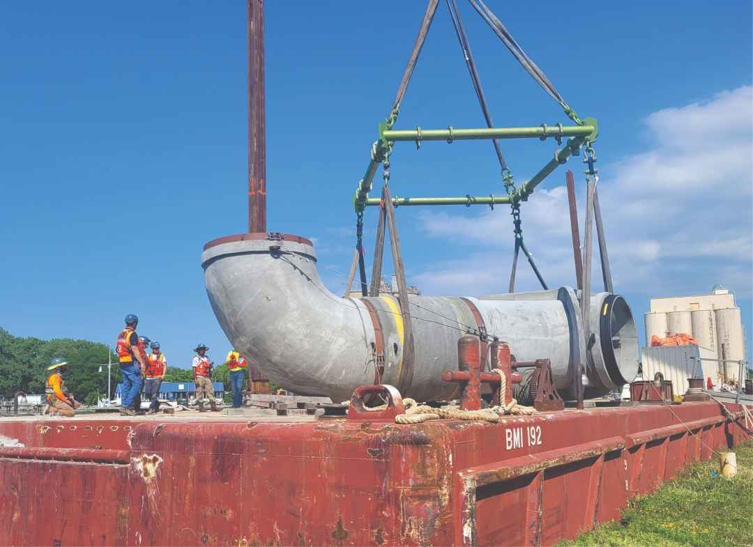
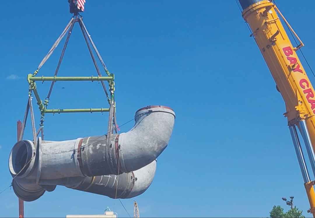
To meet those exacting requirements, Dearborn designed the rigging system around a rectangular modular spreader frame (CMOD) that could be resized to accommodate each component’s dimensions.
The frame’s nominal size was 11 feet by 11 feet, but on this job, it was used as large as 13 feet by 13 feet and as small as 11 feet by 11 feet.
“Using the CMOD to lift the tridents and Cross T center box enabled balanced four-point vertical connection to the load, which minimized any chance of lateral stress,” said Walsh.
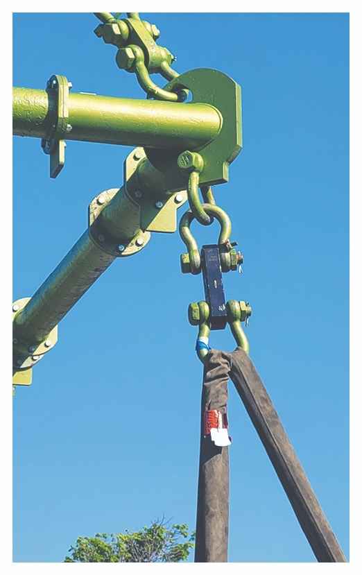
Each of the CMOD’s four corners was connected to the crane’s hook by a 15-foot synthetic round sling and to the load below by a wireless load cell and a 30-foot synthetic roundsling configured in a basket hitch.
“We selected synthetic round slings and basket-hitch configuration to provide a relatively soft point of contact with the pipe wall,” Walsh said. “And we deployed the load cells to verify and monitor load balance and the force applied to the pipe.”
He added that the load monitors were placed between the CMOD and the slings supporting the load in order to measure the forces most accurately.
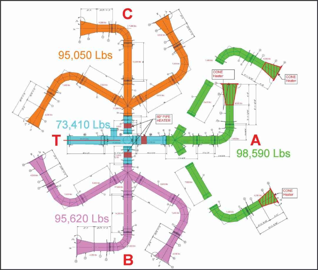
the Cross T section that they connect to is blue.
“As a matter of good engineering and rigging practice, it’s best to place the load cell as close to the force point as possible,” he said. “In this case, it was particularly important that we closely monitor all four points of connection as accurately as possible.”
The rigging also included four come-alongs to permit fine tuning of the load balance, as the actual center of gravity was not precisely known, and was different for each component.
Walsh said that the sling lengths were chosen to provide calculated sling angles and maintain specific hook heights at given lifting radii.
The two sections of pipe that weren’t lifted using the rectangular CMOD spreader frame were pieces of the Cross T connector that needed to be lifted separately from the connector’s center box to avoid undue stress on the components and joints.
But even those two straight pieces of pipe got kid-gloves treatment.
They were lifted using a 37-metric-ton capacity lifting beam and synthetic round slings in basket hitches.
“Using the lifting beam for those pieces eliminated the need to reconfigure the CMOD for those picks,” Walsh said. “And it still enabled using basket hitches. The pipe was too sensitive and critical to risk simply choking the short straights with a single sling.”